Influence of discontinuity on rock mass behavior
Planes of discontinuity define the strength, deformational and hydraulic properties, and the general behaviour of rock masses. The discontinuities make the rock mass discontinuous and anisotropic, meaning it is weaker and more easily deformable, which makes it very difficult to assess its mechanical behaviour in the context of engineering work. Discontinuities allow water flow and provide preferred planes for weathering and fracture (Figure 1). It is essential to describe and characterize discontinuities in a study of the mechanical and hydrogeological behaviour of the rock mass. The stability of excavations and foundations in rock, for example, depends on the direction and strength of the discontinuities.
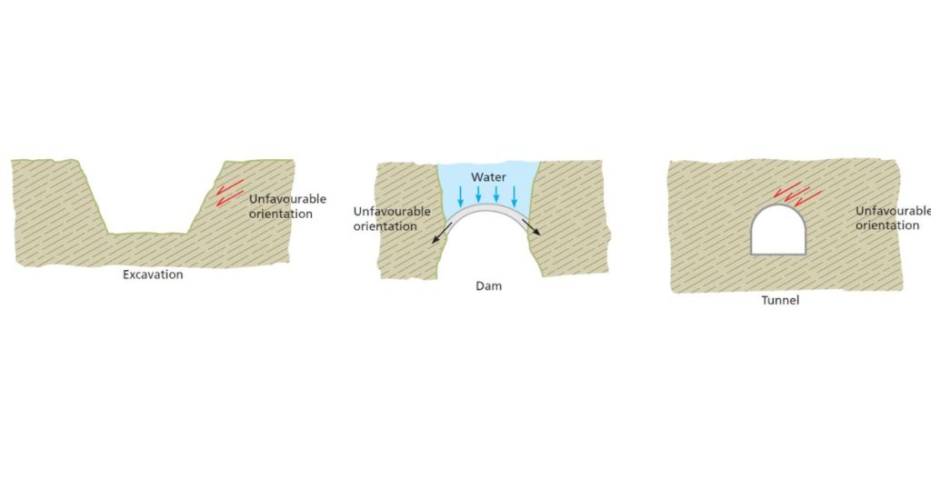
In engineering work for excavations or foundations, the relative orientation of discontinuities may determine whether the ground is stable or not, as shown in Figure 2. In surface excavations the stability of a slope depends on its orientation in relation to discontinuities; in arch dams, the presence of discontinuities parallel to the direction of the resultant force transmitted by the dam and the water may cause problems of stability; in tunnels, discontinuities with pronounced dips running parallel to the tunnel axis are equally unfavourable. Orientation is even more important if there are other factors, such as a large number of joints, of close spacing and low angles of friction. When various sets of discontinuities are present, in different directions, they will determine the level of fracturing in the rock mass and the shape and size of blocks of intact rock.
Shear strength is the most important aspect to consider when determining the strength of jointed hard rock masses. A description of the physical and geometrical characteristics of the planes is required to evaluate the shear strength, as laboratory or field tests alone do not always give satisfactory results.
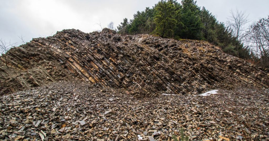
Discontinuities are grouped into families or sets characterized by their average representative values for their orientation and strength characteristics. Discontinuities in the same family are parallel or sub-parallel to each other (Figure 3). Single macro-discontinuities are sometimes present, running through the whole rock mass in addition to the other different sets; these should be studied on an individual basis.
Types of discontinuities
The term discontinuity refers to any plane of separation or weakness in a rock mass; its origin may be sedimentary (bedding or lamination planes), diagenetic or tectonic (joints and faults). In Table the different types of discontinuities have been grouped as “systematic”, when they appear in sets, and “singular”, when there is a single plane running through the rock mass; the latter type is usually more continuous and persistent than systematic discontinuities and may be up to several kilometres long in the case of faults. While sets are classified statistically by their average orientation and by their general characteristics, singular discontinuities require individual description and treatment. They may even influence and control the mechanical behaviour of a mass to a greater extent than the systematic discontinuities.
Types of discontinuities
| Discontinuities | Systematic | Singular |
|---|---|---|
| Planar | — Bedding planes — Lamination planes — Joints — Foliation planes | — Faults — Dykes — Discordances |
| Linear | — Intersection of planar discontinuities — Lineations | — Axes of folds |
Joints
Joints are the most usual discontinuity planes in rock masses. These are fracture or failure surfaces in the rock along which there has been little or no displacement. They affect all types of rock and can be classified by their origin:
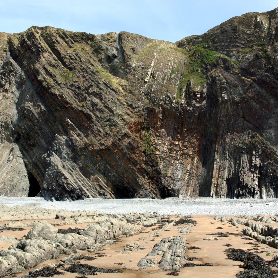
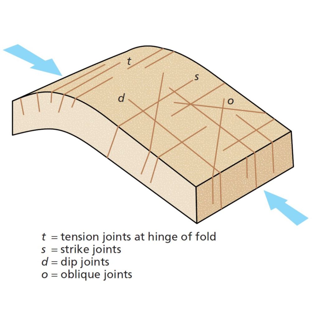
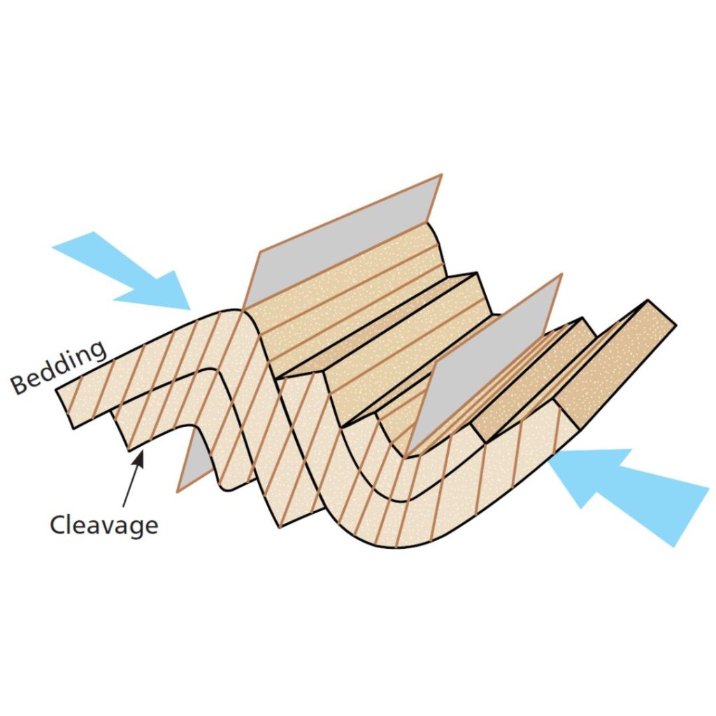
— Joints of tectonic origin, associated with folds and faults. Joints associated with folds have a characteristic arrangement (Figure 4). Joints associated with faults are parallel to the fault surface and they become less frequent the further they are from the fault.
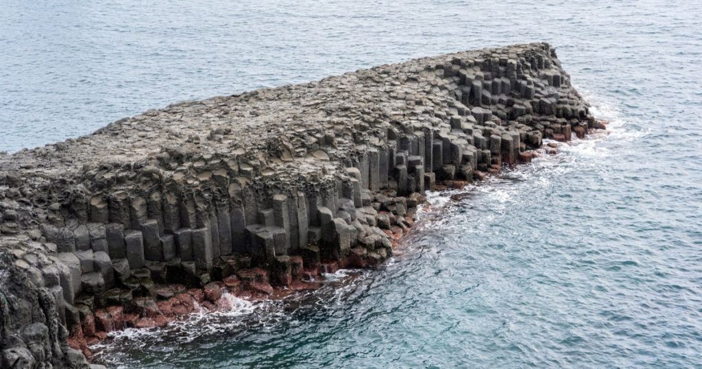
— Joints in igneous rock, caused by contraction of the igneous body during or after its emplacement. These have a characteristic arrangement in three mutually orthogonal sets. An example of joints caused by contraction during cooling is the columnar jointing that forms in basaltic lavas from tensile cracking (Figure 5).
— Relaxation joints, the result of a reduction in lithostatic load on the rock mass. These are arranged subparallel to the topographic surface and become less frequent with depth.
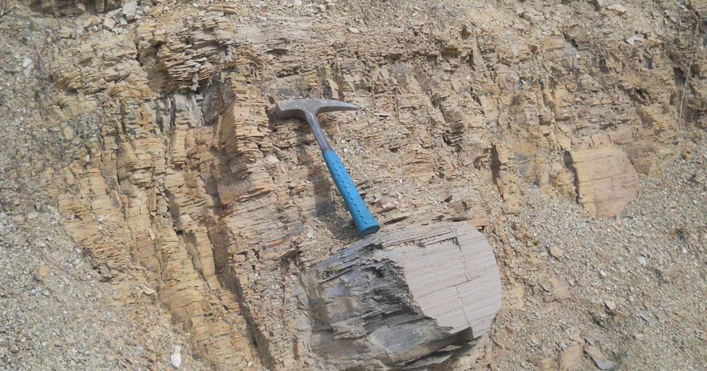
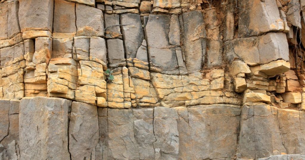
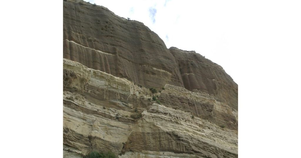
Bedding planes are the surfaces between the beds in sedimentary rocks (Figure 5). These systematic discontinuities extend over a wide area, with spacing generally ranging from a few centimetres to several metres.
Lamination planes are systematic discontinuities found in sedimentary rocks and are the surfaces separating the layers or smallest megascopic levels in the sedimentary sequence (Figure 6). These surfaces are more significant in fine-grained rocks and are characterized by very close spacing, of a few millimetres or centimetres.
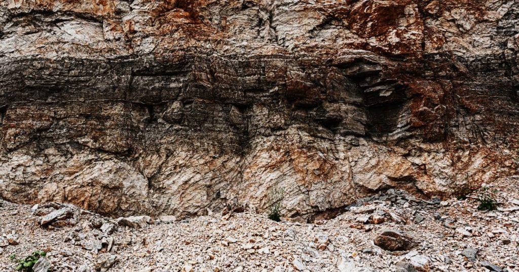
Foliation planes have tectonic origin and occur in rocks that have undergone considerable deformation. They are arranged perpendicularly to the maximum compressive stress operating at the time of their formation. The smaller the grain of the rock, the more likely these systematic discontinuities are to develop, with high frequency and millimetric spacing (Figure 7).
Lithological contact surfaces are singular separation planes between different lithologies in a rock mass. In unfolded sedimentary rocks, they can be less important to the behaviour of the rock mass as a whole than other features, and are simply considered as bedding. In folded sedimentary rocks they can be surfaces of syn tectonic shear and very important to the behaviour of a rock mass. Contact surfaces in igneous rocks are very important, especially in dykes and dyke rocks (Figure 8).
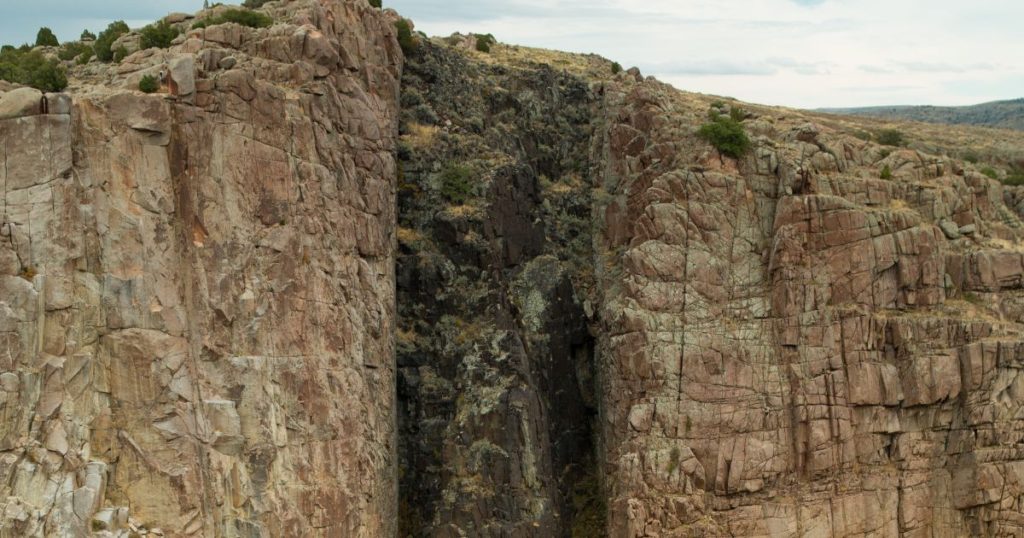
Faults are singular discontinuities corresponding to failure or fracture planes that show relative displacement between the blocks (Figure 8). The size of the faults may vary from a few metres to hundreds of kilometres. They may be associated with areas of weakness known as fault zones or breccia where a clearly defined fracture plane cannot always be distinguished.
Thank you for sharing it is very interesting
Thank You.
[…] The readings from the first and last 15 cm section should not be considered, in the first case because of soil disturbance and wall collapse, and in the second because of possible over-compaction. The penetration resistance N is the number of blows required to drive in the split spoon for the two middle 15 cm sections (30 cm total) of penetration. If the advance or penetration of the sampler is very slow, or rebounds due to the strength of the ground, and more than 100 blows are needed for the sampler to advance 15 cm, the test is discontinued. […]
[…] test is used to estimate the angle of friction of discontinuities or basic angle of friction for smooth discontinuities to allow calculation of the residual angle of […]
[…] maps, indicating average strike values and the dip direction, and value for different types of discontinuity (joints, faults, foliation, […]