Rock falls
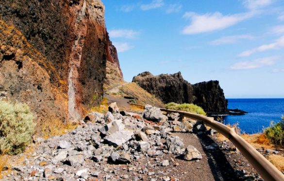
Rock falls are very quick free falls of rock blocks which are dislodged from pre-existing discontinuity planes (tectonic, bedding surfaces, tension cracks). The movement may be by a vertical fall, by a series of bounces or by rolling down the slope face. They are common on steep slopes in mountainous areas, on cliffs and in general on rock walls; the blocks are bounded by different sets of discontinuities, often forming wedge shaped blocks. The factors that cause them include erosion and loss of support for previously separated or loosened blocks in steep slopes, water pressures in discontinuities and tension cracks and seismic shakes.
Figure 1 shows different types of rock falls (Figure 1).
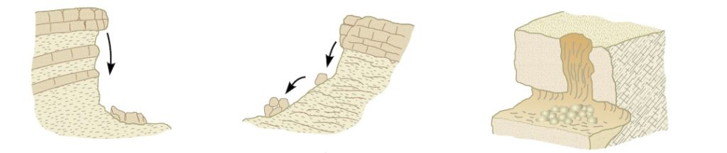
Although the fallen blocks may be relatively small in terms of volume, rock falls are sudden processes that pose an important risk to communication routes and buildings in mountainous zones and at the foot of steep slopes.
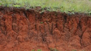
Masses of soil may also fall from vertical natural and excavated slopes, generally due to the existence of tension cracks generated by tensional stresses or shrinkage cracks in ground that has dried.
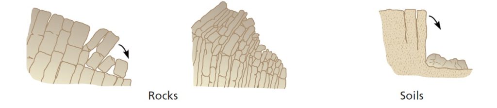
Toppling of strata or blocks of rock may be included in rock falls. Toppling occurs when the strata dip in the opposite direction to the slope, and also forms naturally inclined blocks which are free to rotate because of failure at the foot of the slope. Toppling tends to occur mainly on rocky slope faces which intersect steeply dipping strata (Figure 2).
Rock avalanches
Rock avalanches, called rock falls or complex movements in some classifications, are rapidly falling masses of rock and debris that detach themselves from steep slopes, sometimes accompanied by ice or snow (Figure 3). The rock masses disintegrate during their fall and form deposits of very different block size, with no rounding from abrasion, and a chaotic distribution. Rock avalanche deposits are unstructured and have great porosity.
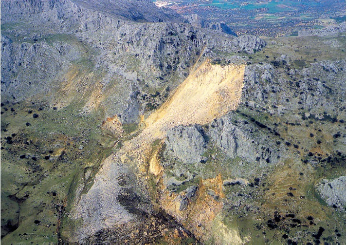
Avalanches are generally the result of large-scale landslides or rock falls which, because of the steep gradient on which they form and the lack of both structure and cohesion in their materials, travel down steep slopes at great speed.
Sometimes, speeds of over 100 km/h are reached, even when the masses are completely dry, because of the reduction in friction caused by the presence of air between the rock fragments.
Water from precipitation or thaw, seismic movements and volcanic eruptions may each play an important role in triggering these processes.
Debris avalanches are formed from rock material containing a great variety of sizes, and may include large blocks and abundant fines. The material forming moraine deposits is prone to these processes, as well as the loose materials resulting from volcanic eruptions. The main difference with debris flows, apart from water content (which is not necessary in avalanches), is the rate and speed of movement of the avalanchee in areas of steep gradients.
Stabilisation and protection against rock falls
Active measures or stabilising procedures to prevent potential rock falls are also described, which consist of:
— Installing bolts and anchors to tie the blocks to more stable ground.
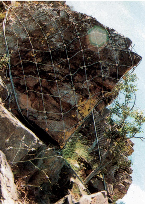
— Installing systems of metallic cables and wire meshes, fixed or anchored to the slopes to stabilise heavily jointed areas; this consists of installing a double or triple torsion metallic mesh, overlaid with a series of cables forming a grid, anchored to the rock at the edges and tightened (Figure 3).
Other types of action, known as passive measures, are aimed at avoiding the damage rock falls may cause to buildings, structures and communication routes. These consist of:
— Metallic meshes to hold small loose rock fragments.
— Ditches or collection areas to trap the fallen blocks.
— Walls and earth ridges.
— Static barriers to brake and contain the blocks.
— Dynamic barriers for the same purpose.
— Artificial tunnels on roads and railway lines.
Control mesh, made of steel wire, is hung from the head of the slope, covering the whole surface to the foot. It is used to “guide” the rock blocks as they fall, preventing them from bouncing and rebounding outwards, so that they pile up at the base where they can be removed. This is effective for blocks smaller than approximately 0.5 m3. Hexagonal, triple torsion, galvanised steel mesh is the strongest.
Ditches or collection areas are dug at the foot of the slope to catch rock blocks. Their width and depth depends on the expected volume of the blocks. They are not effective if the rocks bounce away from the slope surface as they fall, as happens in areas of uneven gradient and hard materials.
To ensure the blocks are stopped a layer of gravel or earth is spread in the bottom of the ditch. A catch fence or mesh barrier can also be used to prevent the blocks bouncing clear of the ditch.
Walls made of concrete or gabions, stop loose blocks advancing and are generally built at the foot of slopes. The disadvantage of rigid walls is that they break more easily on impact. Earth ridges can also be built in a trapezoidal form.
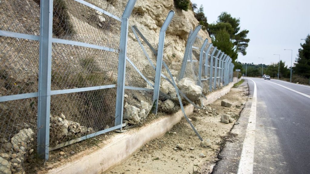
Static barriers are used at the base or on the surface of a slope to intercept and stop blocks. They are normally made of metal posts driven or built into the slope and fitted with resistant wire mesh (Figure 6).
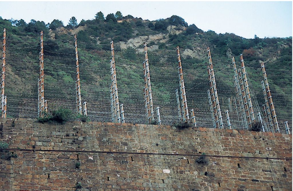
They can also be made with metallic beams, placed close enough together to prevent falling blocks passing between them. Like the rigid walls, they may be damaged by heavier blocks than they were designed to withstand.
Flexible or dynamic barriers are able to absorb the impact energy of the blocks through elastic and plastic deformations of the metallic mesh and other components of the barrier. They consist of twined steel cable mesh, supported by steel posts founded and anchored to the slope, and linked to each other by cables (Figure 7).
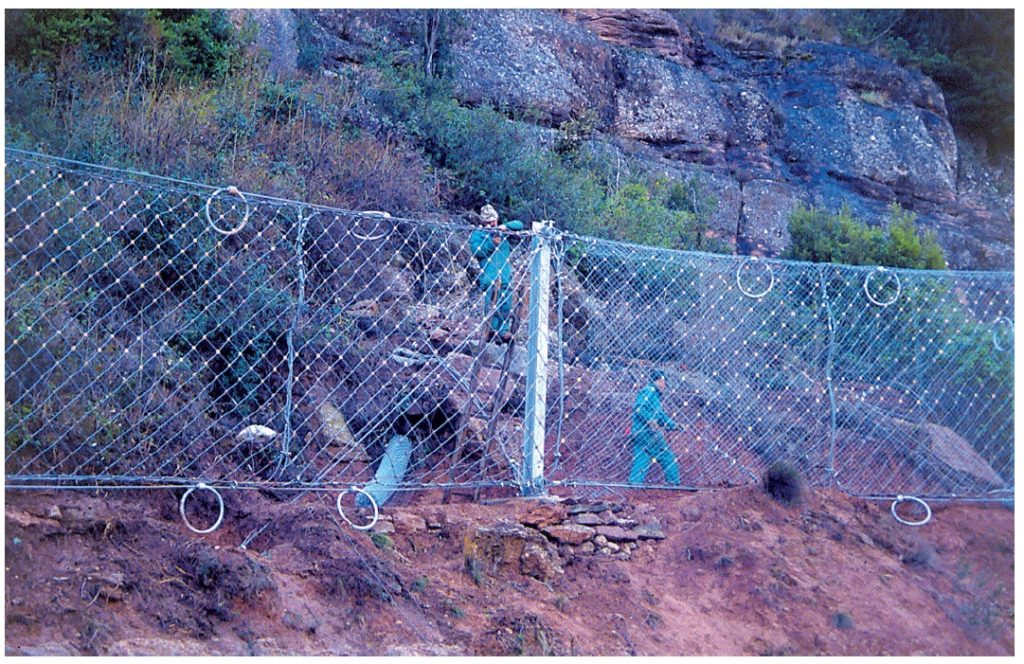
The system is based on the deformation capacity of the mesh and cables and on the built in braking systems which come into play on the impact of the blocks, with an energy absorption capacity of up to 5,000 kJ. They are normally installed leaning away from the slope and 3 m high, although they may be higher. These barriers are designed on the impact energy of the blocks and their size, speed and trajectory. These barriers can also be installed above a portal of tunnels to brake the free fall of large blocks (Figure 8).
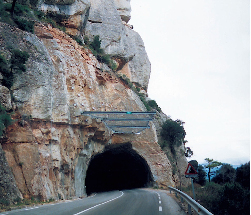
Artificial tunnels also protect roads and railway lines against rock falls. They are built of concrete and a layer of granular material is laid on their roof to cushion the impact of blocks and prevent them from bouncing.
If the volume of the rock blocks is relatively small, then lighter structures or dynamic galleries can be used instead of artificial tunnels.
The measures mentioned above are designed on the quantity, volume and weight of the blocks, the gradient and trajectory of the blocks, their impact energy and distances they can reach, the level of potential risk of rock falls, accessibility of the slope and the space available to install them.
Field observations and measurements provide the most reliable data for the choice and design of the most appropriate solution, and a combination of several is often used. Estimating the parameters mentioned above is very important, especially when installing barriers and walls, to ensure that they are not damaged significantly and that the blocks do not go over the top of them if they bounce on the slope, or in the zone between the foot of the slope and the catch barrier.
There is specific computer software (e.g. ROCKFALL, ROTOMAP) which can be used to simulate the trajectory of blocks from a slope having a given geometry, source areas of given location and blocks of given size and shape for the materials forming the slope, and other variables. The results from the simulation will define the position and height of the barrier or wall. When the height of the barrier and the distance to the foot of the slope where it has to be installed, to ensure it brakes any possible rock fall, are not acceptable (because it is too high or there is not enough space) then these two parameters (position and height) are decided from probabilistic analysis, assuming an acceptable level of risk of potential damage. Intermediate mid-slope barriers can also be installed depending on the gradient of the slope, the location of the source areas and access.